|
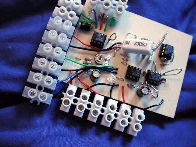
the finished version with terminal plugs installed. plugs on the
bottom are for 3 power supplies - there's a jumper for the optional
3rd - the top left are for the optics and coil, and the top right
are for the power transistor |
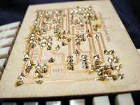 |
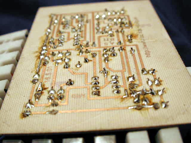
here's the belly of the beast |
 |
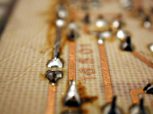
this shows the date of the design |
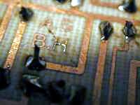 |
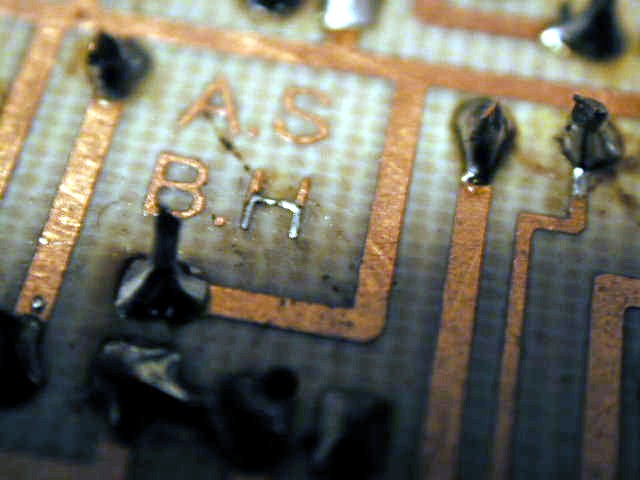
these are the initals of the creators of the maglev pcb - Amadeus
Stevenson and Barry H |
 |
another view of the belly, you can just about see the mark number
in the top left corner |
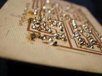 |
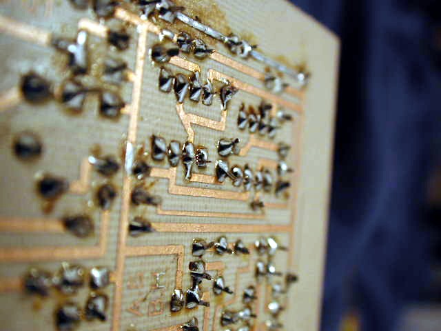
a nice view of the tracks on the pcb, and a glimpse of the website
imprinted in copper |
 |
more tracks, view of initials... |
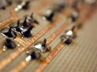 |
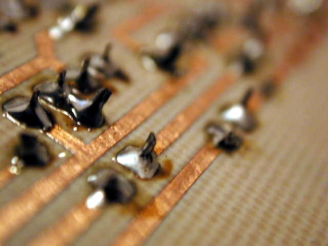
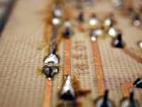
even more tracks - close up of soldered something-or-other |
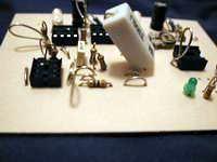 |
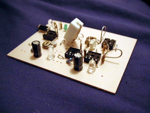
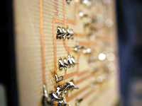
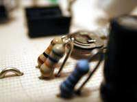
a pre-terminal plugs view of the pcb, the white thing is a hefty
3W power resistor, the loops of bare wire are the test points for
the chips. |
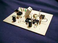 |
another pre-terminal view, from different angle, the leds on the
top left show when the coil is on or off. |
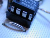 |
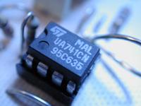
close up of a trusty 741 and a jumper wire
|
 |
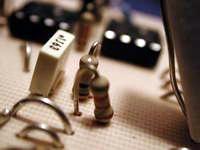
another view of a trusty 741, resistors soldered end up for compact
sake, and a loop of wire for test-probes to test the output of the
chip |
 |
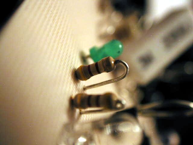
the little green led is on whenever the coil is off - is alternates
with the other led (red when coil is on), and is great to see
when the coil is off and when it's on - especially when you're
calibrating the optics
|
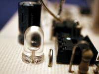 |
this is a power led, it simply lights up red when the power is
on |
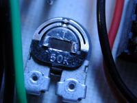 |
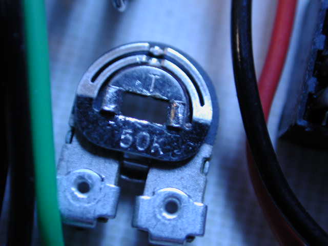
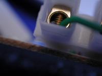
here's the great on-board variable resistor, which is vital in
the calibration for the optics - and as it's on board and solid,
you don't have to fiddle with holding it down with one hand and
shoving a screwdriver in it... |
 |
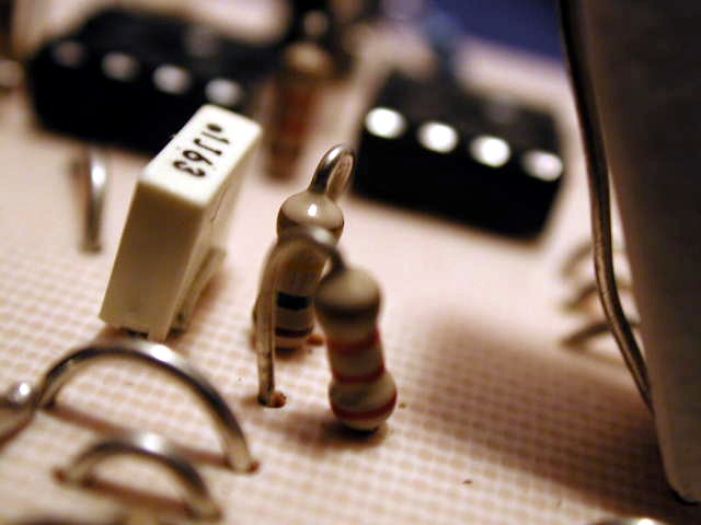
an example of the new compact design - resistors are soldered
vertically to save space... |
 |
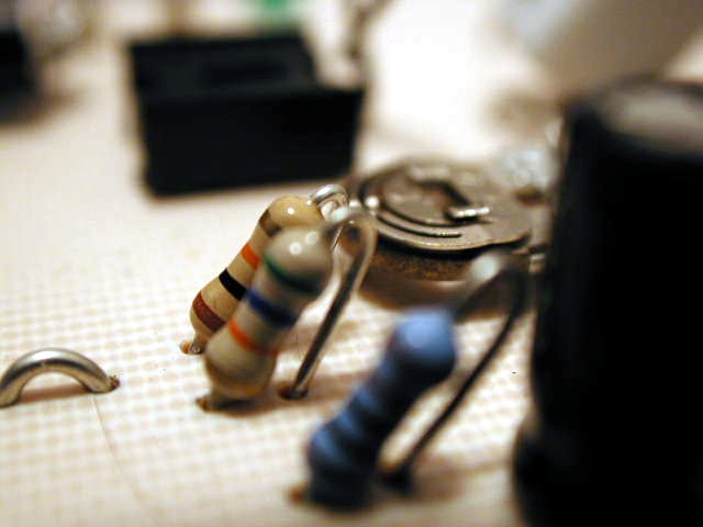
another view of the compact design, the white thing is a ceramic
capacitor, compare the small resistors on the left to the towering
inferno on the right - the white thing... |
 |
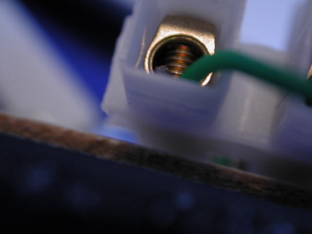
close up of a terminal plug, leading to some useful thing no doubt... |